DIY Roland Jupiter 4 CV/Gate interface
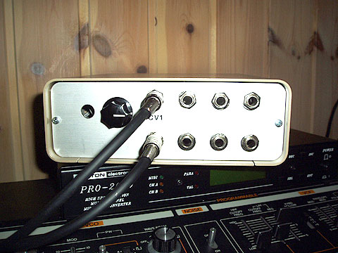
The Roland Jupiter 4 is a fantastic synthesizer, but by default it lacks CV/Gate inputs which makes it difficult to use in a modern studio environment where MIDI is used for seqencing.
In this article I will show you how to build a CV/Gate interface for the Jupiter 4 while keeping the alterations to the original synth to a minumum. Together with a MIDI to CV converter you can then easily incorporate the Jupiter 4 in a modern MIDI based studio.
This project requires that you have some basic knowledge about electronics and soldering.
Table of contents
- Introduction
- The schematic
- Building description
- Inside the Jupiter 4
- What do you need?
- The result
- Disclaimer
- Contact
Introduction
Adding CV and Gate capabilities to the Jupiter 4 is not as hard as you might think. Most of the advanced stuff is already there, inside the synth. Basically all you need to do is tap in on the connetion between the key assigner board and the motherboard of the synth.
I have seen a solution described on the Internet where you drill eight holes in your Jupiter 4, put eight breaking phone jacks in the holes, split the connector wires running between the key assigner board and the motherboard and connect the ends of the wires to the jacks. With no plug in a jack the control signal comes from the key assigner board (internal source) and with a plug in the jack, the control signal comes form the external source. This works, but I think it's a bit crude and there are some major problems with it:
- First of all I hate drilling ugly holes in these beautiful old machines and therefore I wanted a solution that didn't require any drilling in the case and as few modifications to the synth as possible.
- Second, the solution described above is not very flexible when it comes to signal routing. For example, you might want to have a single CV/Gate source provide all four oscillators in the JP-4 with control signals. Or, if you have two separate CV/Gate sources (call them A and B), you might want source A to controll two of the oscillators and source B control the other two. Or have A controll three oscillators and B one. Well, you get the idea. With the above solution you won't get this flexibility.
- Thirdly, in the above solution there are no safety nets whatsoever. If you by mistake would patch the wrong kind of signals into the CV/Gate jacks or if there was a short circuit you could easily fry your beloved synth, the unit connected to it or both. Therefore I wanted a safer solution with buffers on all input jacks. (Actually, when I started out with this project I didn't know about this but thank's to a fellow member of the Swedish Analog Enthusiasts I do now. Thank's Daniel!)
- Least but not last I wanted two distinct modes for the CV/Gate interface (keyboard mode and external mode) and a switch that would enable me to switch between them. In keyboard mode all control signals would come from the keyboard of the JP-4 and in external mode all control signals would come from the CV/Gate interface.
The schematic
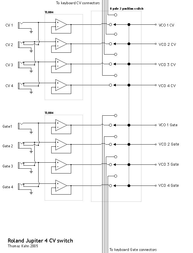
When I knew what I wanted I sat down and drew a schematic of the interface circuit. This is the first circuit ever that I have designed myself so I needed some input and suggestions from more experienced circuit designers. This I got from my fellow members of the Swedish Analog Enthusiasts and the result looks like this:
Building description
Looking at the schematic you see the CV/Gate signals coming in though the jacks. The tip connector of the jack is where the actual control signal enters the circuit and the sleeve of the jack is connected to ground. The ground from the sleeves are all connected to a ground wire in the interface box. Exiting the box, the ground wire goes to the Jupiter 4 where it's connected to GND on the Jupiter 4 power supply board. You need this connection so that the interface and the synth have the same ground reference.
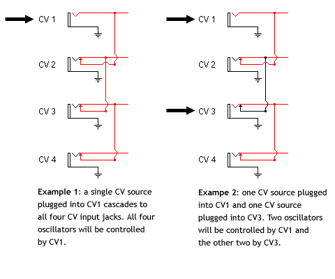
You will need to use breaking jacks so you can solder them together in the cascading fashion shown in the schematic. This means that when there is nothing plugged into a jack, the tip will get its signal from the breaking connector and when there is a plug in the jack, the tip connector of the jack will get its signal from the tip of the plug. If you wire the jacks in this fashion you will get a very flexible signal routing. Here are some examples:
The tip of each jack is then connected to an OP AMP which is wired to serve as a voltage follower. The voltage follower won't alter the value of the incoming voltage in any way, so if you put +1.5 volts into the voltage follower you will get +1.5 volts out as well.

So what is it good for? Well, it will make sure you get a high input impedance on the interface jacks and thereby serve as a buffer. I won't get into details regarding this since I don't know that much about it; let's just say that this prevents your gear from getting fried if something goes wrong.
Since there are 4 CV jacks and 4 Gate jacks you will need a total of 8 voltage followers. I was recommended to use the TL084 chip since it had suitable specifications and each chip housed four separate OP AMP's (one chip for the CV signals and one for the Gate signals).
The TL084 is wired as follows:
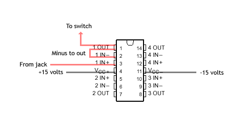
In the above picture only OP AMP number 1 in the TL084 chip is wired, but the principle is the same for all four:
- The tip of the jack is connected to the "IN +" pin on the OP AMP.
- The "IN -" pin is conntected to the "OUT" pin.
- A wire is connected from the "OUT" pin to the switch.
As you can see the TL084 also needs a supply voltage (Vcc + and V cc - ). This voltage is taken from the Jupiter 4 which can supply +/- 15 v. The power supply unit is found at the left end of the synth and in my unit there was a spare socket that I used. The pins on the voltage supply are (top-down): +5 v, +15 v, -15 v, GND, GND. The ones you'll be using are +15 v, -15 v. You will also be using GND, but it's connected to the sleeves of the jacks, not to the OP AMP.

The easiest way to work with the TL084 chips is to solder them to an experiment board and then solder all the wires going to and from the chips (and some jumpers) onto this board. I used an experiment board with 3-hole copper islands which worked fine. Make sure you know which end of the chip is up and which is down while soldering so you don't confuse the chip legs. This might sound obvious to the more experienced builder, but with all the wires and jumpers it's easy to get confused.
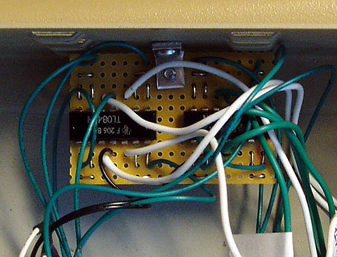
After the CV/Gate signals have passed through the buffers the output from the 8 "OUT" pins are routed to the switch. This switch should have two positions: one for keyboard mode and one for external mode. Since there are two groups of signals, each consisting of 4 CV and 4 Gate signals that need to be switched, the switch has to have 8 poles.
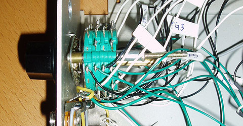
The switch I used was an old computer monitor switch so it had more than 8 poles, but I just used 8 of them. When throwing the switch you either route signals from the input jacks or from the keyboard to the motherboard (the VCO's). You don't see much of how the switch is wired in the image above I'm affraid, but by looking at the schematic you should be able to figure out how to connect the wires to the switch. A word of advice: mark all wires you connect to the switch with paper tags or something because there are a lot of wires and you don't want to connect the wrong wire to the wrong pole.
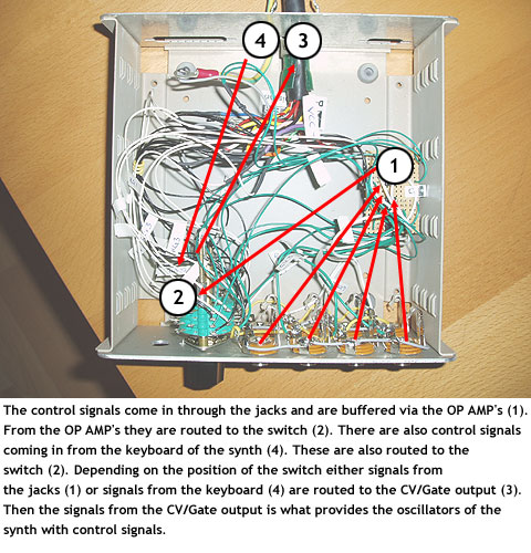
Coming out of the switch are 8 wires carrying the control signals that are to be routed to the synthesizer. Depending on the position of the switch these signals either originate from the input jacks or the key assigner board of the Jupiter 4.
The next step is to connect the interface to the synthesizer. I wanted a solution that could easily be unplugged in case I wanted to transport the synth. I found a couple of old radio communication cables(?) with 18 connectors lying around. I used these for connecting the box to the synth. Using these 18 wires I have room for 4 CV and 4 Gate signals running from the synth (key assigner board) to the interface box, 4 CV and 4 Gate signals going from the interface box to the synth. The remaining 2 wires are used for +15 volts and -15 volts going from the synth to supply the OP AMP's in the interface box with power.
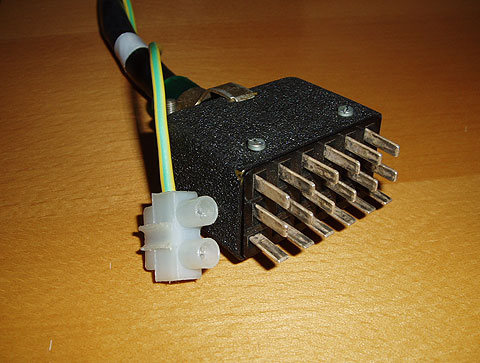
Above, the cable(s) that come out of the interface box...
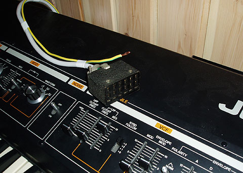
...and here's the cable(s) that come out of the synthesizer. These two are then connected to complete the circuit.
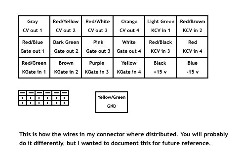
As you can see from the pictures 18 wires was not enough since I needed a ground wire as well. So much for my fancy connection. But for me this was a project where I came up with a lot of the solutions along the way and, hey, at least it works! If you decide to build an interface like this yourself you can learn from my mistakes and get a cable with more wires to accomodate all of the signals in one single cable.
Inside the Jupiter 4
Now let's have a look inside the Jupiter 4 to see what needs to be done there.
If you haven't already done that, remove the small 10-wire connector cable that connects the key assigner board with the motherboard. The cable looks like this:
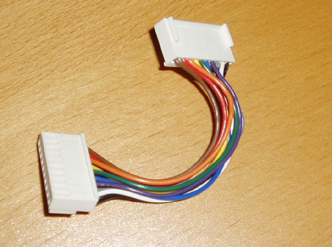
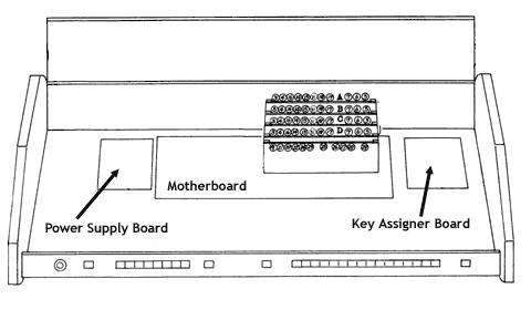
You will find the key assigner board at the far right end of the synth:
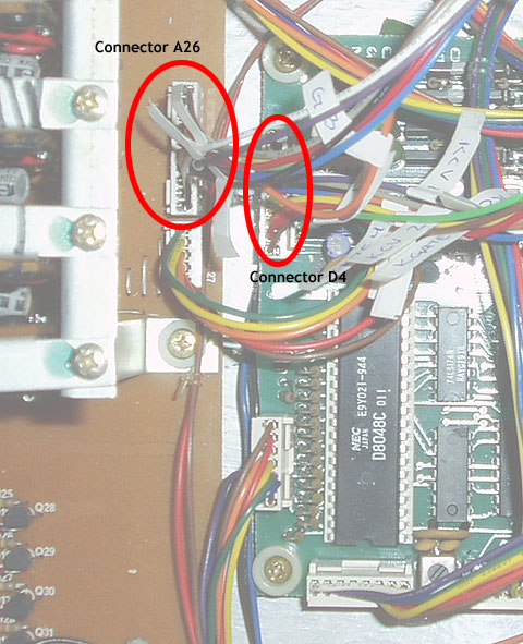
The next step is to plug in two new 10-wire connectors to the sockets on the key assigner board and the motherboard. To these connectors you then solder the wires coming from the interface box. The connector pins on the key assigner board and the motherboard in the Jupiter 4 looks like this:
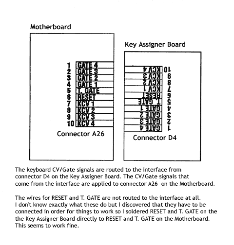
It's important that you solder the right wire to the right connector inside the Jupiter 4 so it's a good idea to mark the wires with small tags here as well.
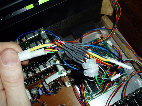
When I soldered the wires from the interface to the two 10-wire connectors inside the Jupiter 4 I used shrink tube around the area where the soldering joint was. This is to prevent short circuits.
So where does the connector cable enter the case of the Jupiter 4? The Jupiter 4 that I own had already been modified by the previous owner. He had moved the oscillator tuning pots from the back of the synth to the top and therefore there was a big hole in the back of the case where the connector cable could easily be fitted:
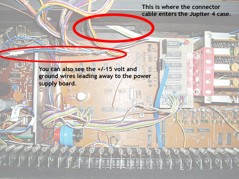
Your Jupiter 4 probably looks different and it's up to you to find a suitable entrance for the interface connetor cable. If you have to drill a hole, do it somewhere on the back and the most important thing of all: FIT THE CABLE THROUGH THE HOLE IN THE CASE BEFORE SOLDERING ANYTHING TO IT! If you don't, you won't be able to get it through the hole later on.
What do you need?
So what do you need to build an interface like this? You need some basic tools of the trade like a soldering iron, soldering led, a pair of pliers, wire cutters and a couple of screwdrivers. You will also need this:
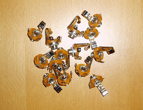
Eight breaking phone jacks. I used cheap ones I had laying around (above) but recommend you use some of better quality.
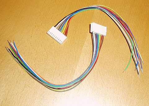
Two 10 wire connectors. Unless you want to cut the cable that is already in the Jupiter 4 you will need two new connectors with cable. If you are unsure of what kind you need, open up your Jupiter 4 and look at the cable that connects the key assigner board with the motherboard.
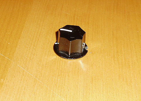
A knob for the switch. :-)
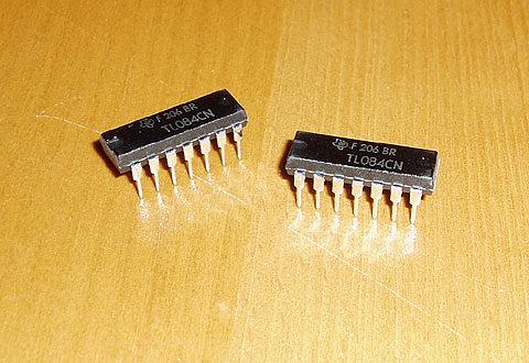
Two TL084 OP AMP chips. I soldered mine directly to the experiment board, but you could mount them using sockets as well. If you want to use sockets you will need 14 pin ones.

Wire. I used a small standard connecting wire for the wiring inside the interface box.
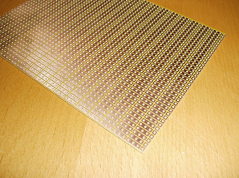
Experiment board or veroboard for connecting the OP AMP's.
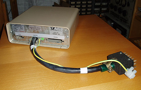
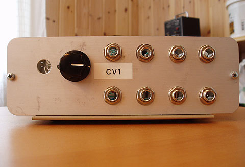
A case and cable(s) to connect the interface to the synth. I used an old modem box and drilled the holes for the jacks and the switch in the aluminum front panel. The cable was an old 18 wire cable that I had laying around and I attached an extra cable for the ground connection. You will need at least 19 wires in the cable though.
Last but not least you will probably need som shrink tubing when you solder wires together. Sorry, no image. ;-)
The result

This thing works great! I use it together with a MIDI to CV converter from Kenton Electronics (Pro-2000) and a computer sequencer. If you have several options for how much voltage to send as a Gate signal from your MIDI to CV interface, the Jupiter 4 seems to want 15v. I have not seen this in any specifications, but I have tried with both 5v and 15v and when using 5v it just sounds faint and wierd. With 15v Gate it sounds much better!
There are a couple of things that I would like to have done differently in this project. First of all I wish I had used better jacks. Mine are cheap which means they are unreliable; especially the breaking connectors. Then there is the cable - I wish I would have discovered that 18 wires were not enough earlier on in the process, but unfortunately I didn't.
I know that this interface has no influence on the actual sound of the Jupiter 4, but I just thought you might like to hear a small MP3 sample of the interface in use. This sound snippet is from an unprocessed (well, the LFO sweeps the filter a bit) Jupiter 4 and I have connected the interface so that one CV/Gate source controls two of the oscillators and another CV/Gate source controls the other two (a 2x2 setup).
Disclaimer
If you decide to modify your Jupiter 4 you do it on your own risk. I can't guarantee that this description is correct in every detail. If something goes wrong I take no responsibility whatsoever. If you have no prior experience of soldering and electronics I suggest you get someone with more experience to help you.
Contact
Feel free to send me an email if you have suggestions for improvements or if you find errors in this project. If you have built an interface of your own it would be great if you would send me an image or just drop me a line. However I can't guarantee that I can answer questions or help you with your project if you get stuck since my time is limited.
I hope you have found this project interesting!